|
2011-12-31
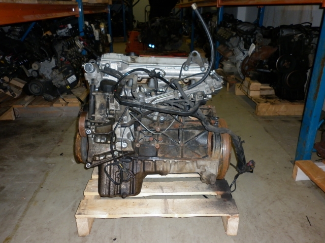
The next step is to swap the engine M102.062 to M111.944. The new engine
is from a 1999 year model C200 Kompressor with 141 kW and 270 Nm (and
about 100000 miles).
Here are a few pics of the new engine.


2012-02-06
The engine bay looks like this when empty

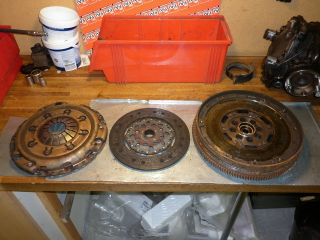
I took off the double mass flywheel.
The flywheel and clutch weighed together about 46 lbs (21 kg). The M102
custom flywheel and the custom clutch weigh about 28 lbs (13 kg) together,
so the setup is about 18 lbs (8 kg) lighter. I hope there won't be
problems with the idle.
Comparing the two engines:
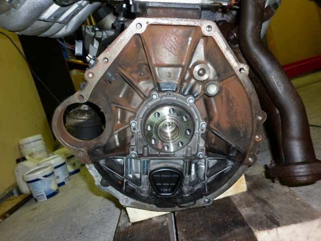
First the M102
.. then the M111
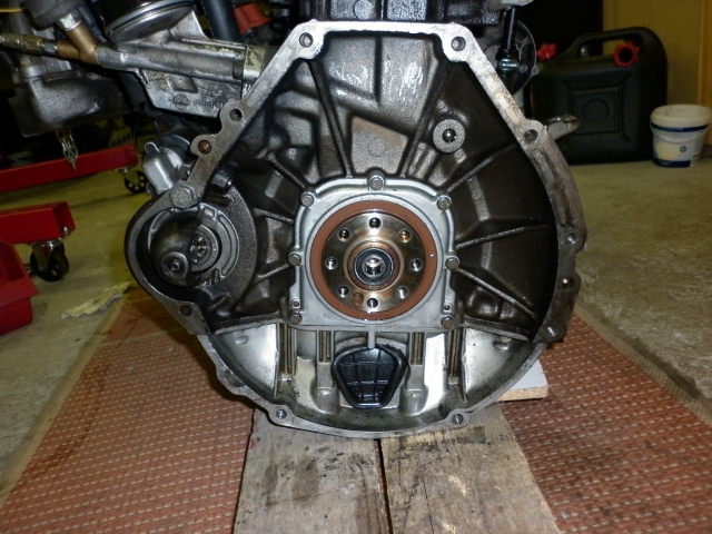
...and finally the M111 with the M102
flywheel. The starter is from the M111. Everything seems to fit including
the TDC sensor.

2012-02-11
The engine build is progressing. Here is the new 90 ampere alternator...

...and here is the flywheel and SRE
clutch from the M102 in their new place...

The engine M111 and transmissiion 717.435
fit together fine, this pic is from the right side...

...and the same from the left side with
the intake, manifold, injection equipment and the electrical wiring
removed

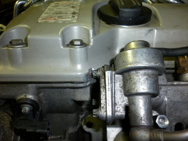
There was no oil pressure sensor in the
M111 engine (!), but a M12x1,5 screw can be changed to the M102 sensor.
The screw is in a bad spot so I must take off the right engine support to
be able to tighten the sensor! The engine front supports are from some
diesel engine so far although the best supports should be in models W124 E200 tai E220
which are not so easy to find.

2012-02-12
More pics.
The intake manifold and the fuel rail...
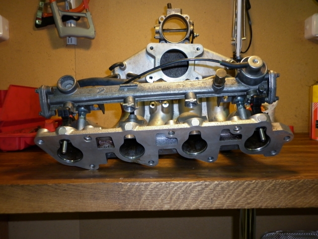
The intake manifold front view...
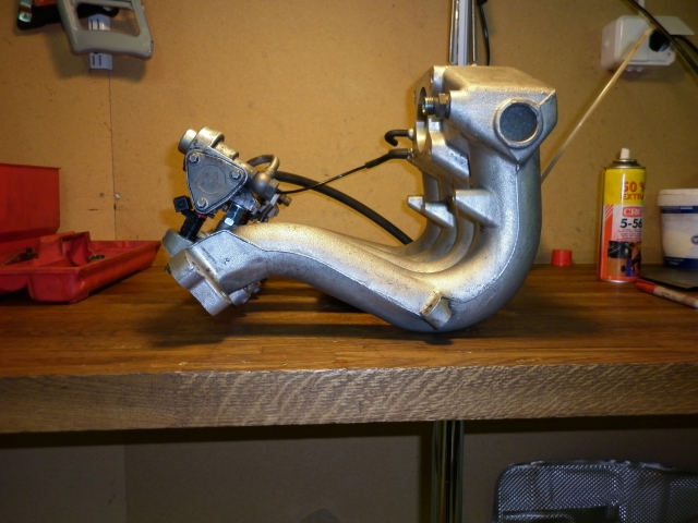
...and rear view...
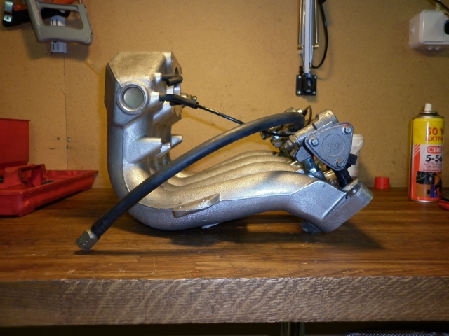
...a clöose-up from cyl nr 1
injector...
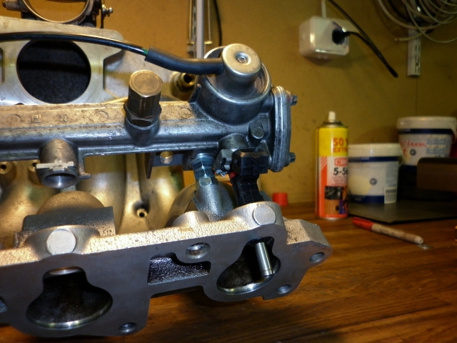
...and cyl nr 4 injector...
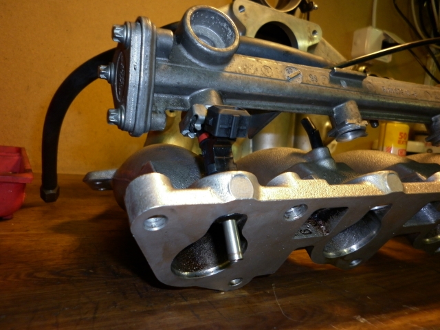
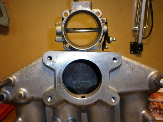
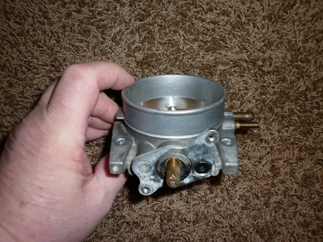
...the throttle plate from the M102 is
58mm and I would like a little bigger one...
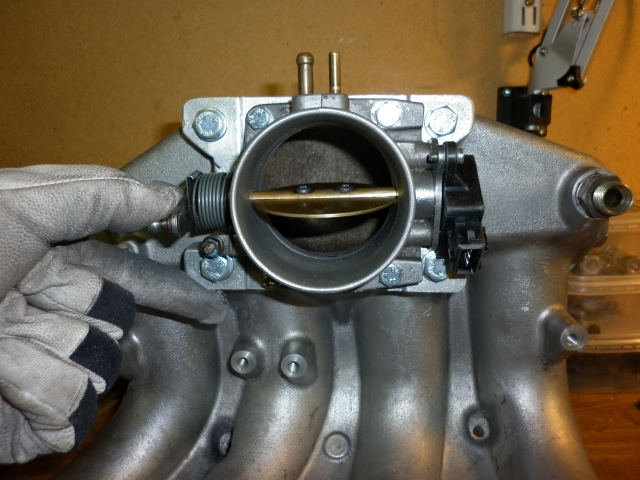
2012-02-22
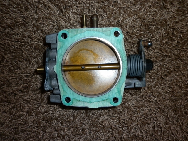
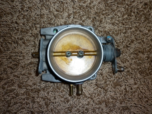
The Volvo 2.56 inch (65mm) throttle plate arrivet, thanks to JuhaU from
Volvo Racing Club Finland.
The outer dimension is about 2.9 inches (74mm) and the Volvo TPS should
fit the plate shaft. I must tune the throttle casing to make it sit on the
intake manifold.
2012-03-03
I lifted the new engine M111 with transmission 717 in the angine
compartment for the first time.There is enough room around the engine but
the alternator touching the anti roll bar when the front wheels are
hanging freely. I must try to fix the problem by changing the position or
form of the anti roll bar.


2012-03-04 (Edited 2012-03-06)
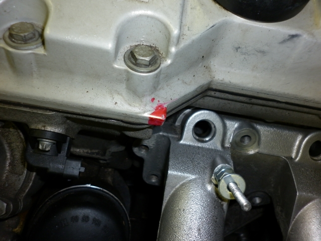
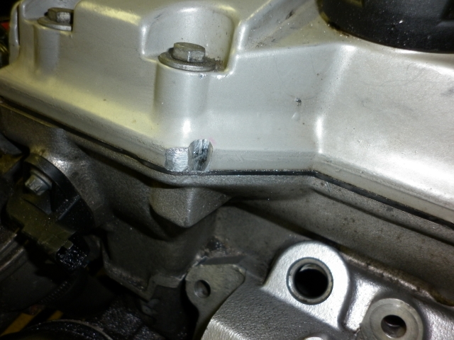
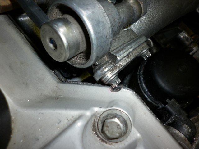
When I was fitting the intake manifold the fuel rail touched the valve cover
because the injectors are shorter than the original ones. I had to modify
the valve cover to make room for the fuel rail screw with a saw and a
file.
2012-03-16
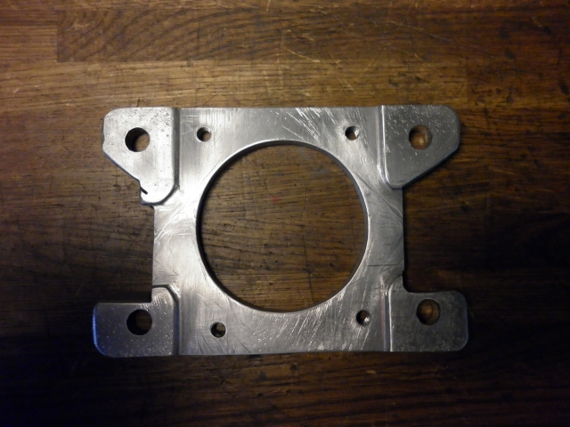
The next job was the new throttle plate. I made a flange between the
intake manifold and the Volvo 65mm throttle plate. I had to turn the
throttle axle 180 degrees to get the TPS in a better position. There was a
fair amount of work with the flange with simple hand tools.


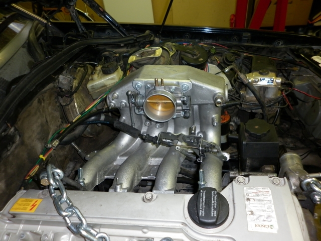
The next job is the new throttle
linkage. Here I am testing the final position of the intake manifold.
2012-03-23
The throttle linkage is ready. The throttle cable is shortened about 4
inches. The linkage is the original M111 turned upside down and positioned
in the cable line.


2012-05-01
The wiring from the ECU and the M111 engine are finally connected. The
engine has two wasted spark coils driven by a copy of the Boschin 0 227
100 200 igbition module. The ECU connection include the cam sensor, the
cam solenoid, the superchaeger bypass valve and the superchafger solenoid
which should be working some day.


2012-05-04
The power steering hose would not fit the new pump. I got help at
Mairuen kone ja pultti Oy (Mairue's
machine and bolt ltd) where the hose end was modified. There I also found
new rubber hoses for the supercharger and the cooling system. Mairue's
shop has good spare parts and a good customer service.


2012-05-19
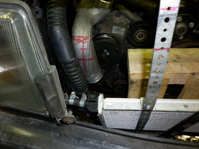
The next thing is to modify the supercharger cover and the intercooler in
order to get the pressurized air to the throttle plate. Here are a
few pics of the job. The cold air intake and the SC bypass valve are in
position. The radiator is in a lower position and the intercooler higher
up to get both in the vcold air stream. Both radiators may get a fan of
their own. The hot air will possibly be routed out via a duct in the low
pressure region of the hood.


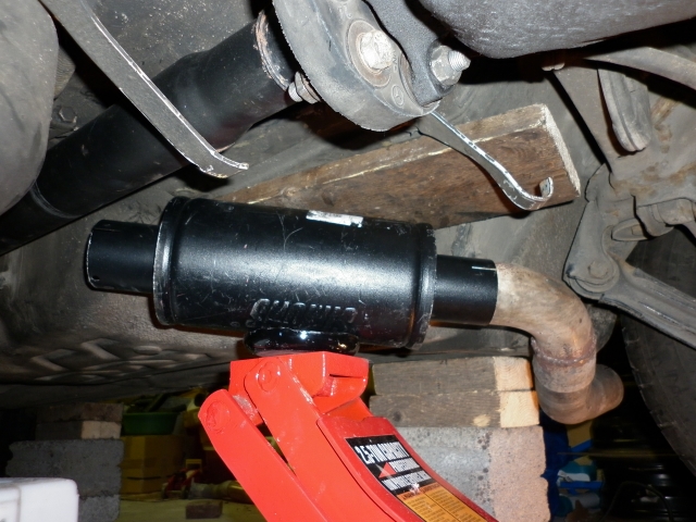
2012-05-23
I will shorten the exhaust pipe and route it out in front of the right
rear wheel. The pipe is 2.5" like before, but the 5" Simons muffler is
only 11" long. If the exhaust sound is too loud I will use an extra
decibel silencer in the tailpipe. The extra silencer is easily detachable
when better btreathing is needed. The tail pipe end needs trimming.


2012-06-05
The fans for the radiator and the intercooler will come from this Ford
Mondeo fan set, The size of the casing is 610 mm x 400 mm and I will cut
it in two halves. The diameter of the fans is 300 mm and thw thickness is
70-80 mm.


2012-06-09
The parts are finding their places. Soon I will start to map the DECS ECU.


Here are a few pictures of the radiator
fan and electric water pump. The water pump will get a mud shield.


2012-07-21
The DECS ECU refused to work with the old two-segment flywheel and a the
M111 cam sensor so I will add a 36-1 trigger wheel in front of the crank
belt pulley. I found the trigger wheel and sensor at
trigger-wheels.com where they
have a good selection of trigger wheels and different kinds of sensors.
The hole trimming (larger center hole and one for balancing) and the D=40
mm, L=100 mm steel support pipe were made by
Lankinen's machine shop, where the
job was quickly made with good quality as always. There will be a gap of
about 1 mm between the trigger wheel and the crank pulley to avoid extra
load on the pulley. The bolt M18x1,5 L160 I found at
ruuvihankinta.fi which also had
a good customer service. The bolt class is 10.9 like the original 55 mm
bolt. Next I have to finish the sensor attachment parts and wires. If the
centering and out of balance will cause judder I must make a better
fastening for the trigger wheel which means more costs again.


2012-07-23
The trigger wheel is in position and this is the sansor bracket which is
fastened with the alternator bolts.


2012-07-26
Finally the engine started after some difficulties with the sensor and its
wiring. Next I must solve minor charging and water leakage problems before
I can start working with the ignition and fuel maps. The trigger wheel
wobbles a little but it so far the sensor seem to work. I might have to
consider a better fixing for it.
The controlling of the supercharger and the variable timing intake cam
needs some adjustment to get them running. Maybe the test runs two weeks
from now come too early because the registration needs some detective
work, adjusting and a little part changing, too.
2012-08-03
I tested the supercharger without the bypass valve with poor results.The
supercharger is charging from idle against the throttle plate and a little
gas pulls the boost pipes off. I must tune the bypass valve so that the
boost comes on softer in the lower revs. The bypass valve will sit on the
original air cleaner. The air cleaner boxt and its intake pipe hits the
water hose so I must modify the position of the pipes.
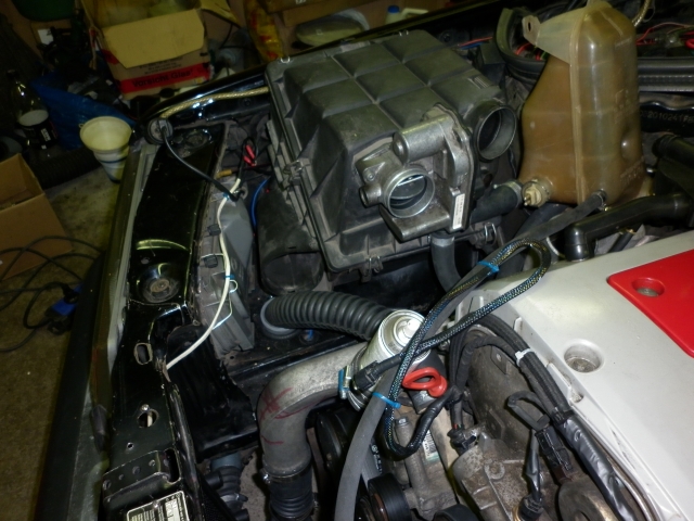


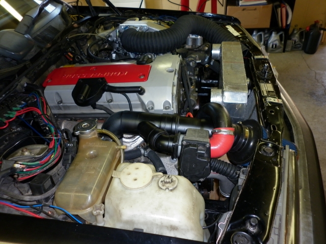
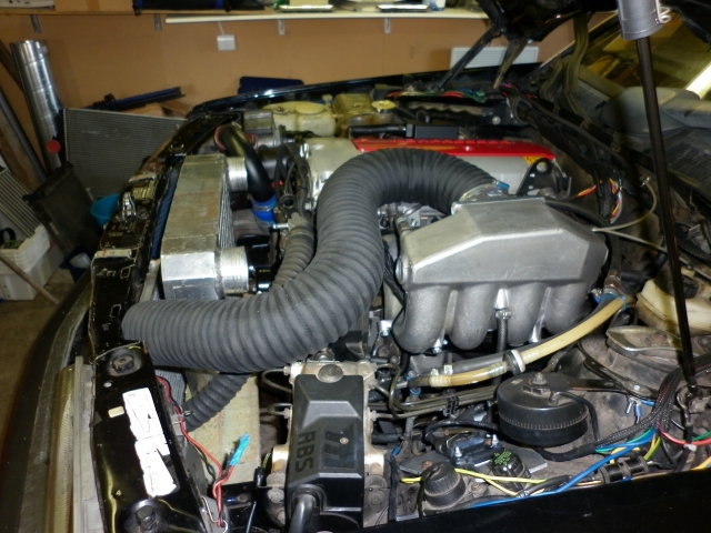
2012-08-07
This is the final package, The cold air pipe from the front grille is
still missing.


2012-09-20
Updating the project. I only had one successful test this summer at a one
mile pull from standstill. The quartermaile intermediate time was just
under 16 seconds and the one mile trap speed was 118 mph (190 km/h). The
quartermile was about half a second slower than with the old engine and
manual box and the one mile speed was about 11 mph (18 km/h) slower than
with the old engine and automatic box. I have some problems with the
intake cam edvance mechanism which is now operated with an on/off switch
and it is on all the time. The bypass-valve is not working and the
supercharger magnetic clutch is controlled by TPS and rpm. The intercooler
is mounted as on the W202 kompressor models but the air flow is not
sufficient so I will put the old turbo intercooler back which means
modifications to the intercooler and the SC outlet pipe. Next winter's job
list also includes the diff swap to 3.46 ASD and making the gearchange
mechanism more accurate.
Anyhow I need more boost / airflow so I
bought this pulley kit which spins the SC about 21% faster. I found it on
eBay.de and got it hiome in eight days. I will see the actual effect on
engine power on a dyno or in road tests.


 |